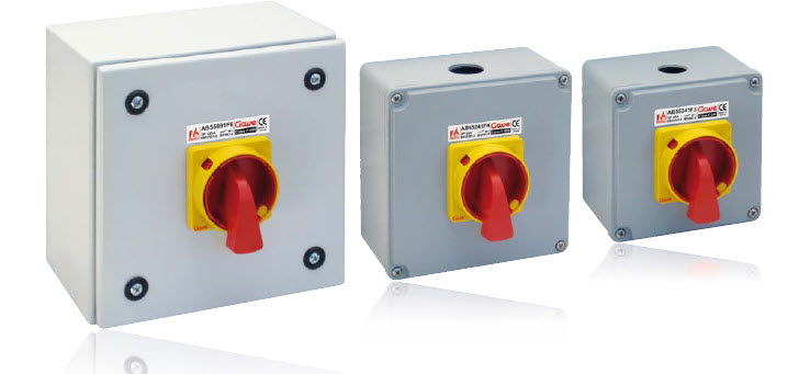
General characteristics
Stringent requirements according to standards EN 12101-3 have originated a highly demanding research task aiming to reach optimal resistance to high temperature operation.
Enclosure
The enclosure has direct contact with the heating source and acts as a firewall diminishing direct heat into the switch.
Advanced materials
High performance polymers mixed with additives succeed to obtain high temperature switches able to resist erosion while offering stable dimensions under high temperature conditions (controlled CTE) while keeping component lubricity and mechanical performance.
• F300 switch can be identified by its Light brown exterior colour. Employed materials offer excellent characteristics to temperature changes.
• The switch body on the F400 and F600 present a larger size containing specific mechanical elements on materials resistant to high temperatures.
• We recognise F400 switches by its external black colour whereas class F600 switches are identifies by its white colour.
IP65 protection
Sealing injected on the enclosure lid ensuring an IP65 degree of protection according to EN 60529

The range of F300 and F400 switch disconnectors share the aluminium enclosures that offer a high IP and IK rating. The F300 range is limited at 40A and the F400 is limited to 125A when using aluminium enclosures. F400 higher ratings (160-250A) use lightweight sheet steel enclosures for easy handling and installation.

The stringent requirements on class F400 under fire conditions require the use of special composite materials that must combine good resistance to extreme temperatures while maintaining electrical characteristics requirements under IEC 947-3 when operating on normal conditions.
Technical Characteristics F300 & F400
| 25A (F3) | 25A (F4) | 40A | 63A | 100A | 125A | 160A | 200A | 250A | |||
| Thermal rating | Ith A | 25 | 32 | 40 | 70 | 100 | 125 | 160 | 200 | 250 | |
| Flexible wire | mm2 | 2,5-6 | 2,5-16 | 2,5-16 | 6-50 | 6-50 | 6-50 | 70 | 95 | 120 | |
| Connection screws | M4 | M5 | M5 | M8 | M8 | M8 | M8 | M8 | M8 | ||
| Screw torque | Nm | 1,6 | 2 | 2 | 3,5 | 3,5 | 3,5 | 12 | 12 | 12 | |
| Terminals | |||||||||||
| Rated conditional | 415V | A | 25/25 | 25/25 | 40/32 | 63/63 | 100/100 | 125/100 | 160** | 200* | 250* |
| kA | 6 | 6 | 6 | 8 | 8 | 8/6 | 8 | 8 | 8 | ||
| short-circuit current | |||||||||||
| Icc (r.m.s.) | 500V | A | 25/25 | 25/25 | 40/32 | 63/63 | 100/100 | 125/100 | 160* | 200* | 250* |
| Max. Fuse size gG/aM | |||||||||||
| kA | 6 | 6 | 6 | 8 | 8 | 8/6 | 8 | 8 | 8 | ||
| Impulse voltage | Uimp KV | 4 | 4 | 4 | 4 | 4 | 4 | 4 | 4 | 4 | |
| Insulating voltage | Ui V~ | 690 | 690 | 690 | 690 | 690 | 690 | 690 | 690 | 690 | |
| Operating rating | Ie A | 25 | 25 | 40 | 63 | 100 | 125 | 160 | 200 | 250 | |
| AC 22 | kW | 3 x 230V | 7,5 | 7,5 | 11 | 18,5 | 30 | 37 | 37 | 45 | 55 |
| Motor load VA kW | 3 x 415V | 15 | 15 | 22 | 37 | 55 | 55 | 75 | 90 | 110 | |
| 0,45 <cosØ <0,65 kW | 3 x 500V | 18,5 | 18,5 | 22 | 45 | 55 | 75 | 90 | 110 | 132 | |
| AC 23 | kW | 3 x 230V | 5,5 | 5,5 | 11 | 15 | 18,5 | 18,5 | 30 | 38 | – |
| Motor load VA kW | 3 x 415V | 7,5 | 11 | 18,5 | 22 | 30 | 37 | 52 | 65 | – | |
| 0,45 <cosØ <0,65 kW | 3 x 500V | 15 | 15 | 22 | 30 | 37 | 45 | 65 | 80 | – | |

Constructing F600 switch disconnectors does require the use of very special materials able to overcome the extreme conditions under this category. The enclosure is on cold-laminated steel resistant to 600ºC temperature.
Developing a particular mechanical block for high temperature has also improved switch behaviour when shortcircuit occurs while keeping the electrical characteristics when operating under normal conditions.
Technical Characteristics F600
| 25A | 40A | 63A | 100A | 125A | |||
| Thermal rating | Ith A | 32 | 40 | 70 | 100 | 125 | |
| Flexible wire | mm2 | 2,5-6 | 2,5-16 | 6-50 | 6-50 | 6-50 | |
| Connection screws | M5 | M5 | M8 | M8 | M8 | ||
| Screw torque | Nm | 2 | 2 | 3,5 | 3,5 | 3,5 | |
| Terminals | |||||||
| Rated conditional | 415V | A | 25/25 | 40/32 | 63/63 | 100/100 | 125/100 |
| kA | 6 | 6 | 8 | 8 | 8 | ||
| short-circuit current Icc | |||||||
| (r.m.s.) | 500V | A | 25/25 | 40/32 | 63/63 | 100/100 | 125/100 |
| Max. Fuze size gG/aM | |||||||
| kA | 6 | 6 | 8 | 8 | 8/6 | ||
| Impulse voltage | Uimp KV | 4 | 4 | 4 | 4 | 4 | |
| Insulating voltage | Vi V~ | 690 | 690 | 690 | 690 | 690 | |
| Operating rating | Ie A | 25 | 40 | 63 | 100 | 125 | |
| AC 22 | kW | 3 x 230V | 7,5 | 11 | 22 | 30 | 37 |
| Motor load VA kW | 3 x 415V | 15 | 22 | 30 | 55 | 55 | |
| 0,45 <cosØ <0,65 kW | 3 x 500V | 18,5 | 22 | 37 | 55 | 75 | |
| AC 23 | kW | 3 x 230V | 5,5 | 11 | 15 | 18,5 | 18,5 |
| Motor load VA kW | 3 x 415V | 7,5 | 18,5 | 22 | 30 | 37 | |
| 0,45 <cosØ <0,65 kW | 3 x 500V | 11 | 22 | 30 | 37 | 45 | |
Reference | Poles | Enclosure size | Cable entries | Rating | |
AB55221F6 | 3P | 1AC | 2xM25 | 25 A | |
AB55241F6 | 3P | 1AC | 2xM32 | 40 A | |
AB55261F6 | 3P | 2AC |
2xM40 | 63 A | |
AB55271F6 | 3P | 2AC | 100 A | ||
AB55291F6 | 3P | 2AC | 125 A | ||
Reference | Poles | Enclosure size | Cable entries | Rating | |
AB55621F6 | 6P | 2AC | 4xM25 |
| 25 A |
AB55641F6 | 6P | 2AC | 4xM32 | 40 A | |
AB55661F6 | 6P | 2AC |
4xM40 | 63 A | |
AB55671F6 | 6P | 2AC | 100 A | ||
AB55691F6 | 6P | 2AC | 125 A | ||